 EN
EN
 AR
AR
 BG
BG
 HR
HR
 CS
CS
 NL
NL
 FI
FI
 FR
FR
 DE
DE
 EL
EL
 IT
IT
 KO
KO
 NO
NO
 PL
PL
 PT
PT
 RO
RO
 RU
RU
 ES
ES
 SV
SV
 ID
ID
 LT
LT
 SR
SR
 UK
UK
 VI
VI
 HU
HU
 TH
TH
 TR
TR
 FA
FA
 MS
MS
 HY
HY
 AZ
AZ
 KA
KA
 BN
BN
 LO
LO
 LA
LA
 NE
NE
 MY
MY
 KK
KK
 KY
KY

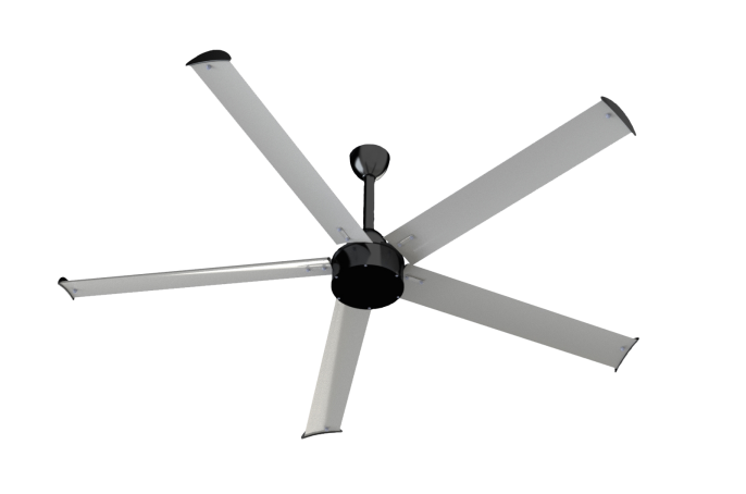
Engineering-Driven Sizing and Placement for Large-Scale HVLS Fans
Why volumetric airflow modeling trumps floor-area heuristics
Rule-of-thumb sizing—such as spacing industrial ceiling fans based on a fixed multiple of blade diameter—overlooks the actual air volume each facility must move. Because a building is a three-dimensional container, a large-scale HVLS fan must be matched to its cubic volume, not just floor area. Volumetric airflow modeling, typically run through computational fluid dynamics (CFD), accounts for full enclosure geometry: height, width, depth, and obstructions that disrupt circulation. A 2022 analysis of 120 industrial retrofits found that CFD-guided layouts delivered 23% lower temperature stratification than those using floor-area heuristics.
The reason is straightforward: a 30-ft-diameter fan may effectively blanket a 20,000-ft² floor in an open hall, but under a 40-ft peaked ceiling, the same unit leaves a doughnut of dead air at the center if its column isn’t sized for vertical throw. Volumetric models first map thermal mass and internal heat gains, then simulate full-volume air exchange. This reveals whether overlapping plumes create destructive turbulence—or whether a single large-scale HVLS fan can suffice. Skipping this step routinely results in 15–30% of work zones receiving inadequate airflow—a shortfall that drives up energy bills and comfort complaints.
Ceiling height, obstructions, and thermal layer dynamics in spacing calculations
Beyond raw volume, ceiling height and overhead structures dramatically alter large-scale HVLS fan performance. Beams, lighting bays, overhead conveyors, and even sprinkler pipes create turbulent wakes that shear the descending air column, shifting effective throw by several feet. When placed directly beneath a deep truss, downflow splits unevenly—producing high-velocity jets on one side and stagnant pools on the other. CFD simulations show that a 6-inch-wide beam at 35-ft height can reduce coverage radius by up to 22% in its shadow zone.
Thermal stratification layers add another constraint. In winter, warm air rises and pools beneath the roof deck; a large-scale HVLS fan must be positioned to draw that buoyant layer down without pulling in cold outside air from dock doors. Ceiling height governs blade-tip speed and mounting bracket length—a fan hung too low in a 50-ft-high bay may never reach the thermal ceiling, while one set too high can stall before air penetrates the occupied zone. Proper spacing therefore integrates the height of the neutral pressure plane, racking or mezzanine profiles, and return-air locations—avoiding the “hot-spot ring” that forms when airflow pushes warm air sideways instead of vertically.
Case study: 42-ft ceiling warehouse with mezzanine — 37% coverage gap corrected via CFD-guided placement
A regional logistics center with a 42-ft clear height and a 120-ft-long mezzanine was initially equipped with four large-scale HVLS fans using a manufacturer’s floor-area formula. Staff reported perspiring in summer and cold drafts in winter, and thermal imaging revealed that 37% of the floor area—including the entire mezzanine underside and loading dock—received negligible air movement. The dead zone corresponded to symmetrical fan placement in the open bay, ignoring the mezzanine’s wind-shadow effect.
After a CFD study, engineers relocated two fans 18 ft closer to the mezzanine’s edge and tilted one unit’s blades by 3 degrees to direct more flow under the platform. The revised layout collapsed the 37% dead zone to under 5% of floor area, verified by follow-up anemometer mapping. The building’s vertical temperature delta—which had exceeded 12°F from floor to peak—dropped to 4°F within four days of commissioning. The project demonstrated that even modest geometry adjustments—shifting fan centroids by a few feet—can recover full large-scale HVLS fan potential, eliminating coverage gaps without adding units.
Aerodynamic Design Essentials of Large-Scale HVLS Fans
Airfoil Blade Geometry, Direct-Drive Torque Efficiency, and Span-to-Volume Optimization
At the core of any large-scale HVLS fan is an airfoil-shaped blade that exploits Bernoulli’s principle: the curved upper surface reduces pressure above the blade, generating lift that drives a massive, low-energy column of air downward. This profile cuts drag by up to 30% versus flat blades, boosting airflow per watt by 20–30%. Direct-drive permanent magnet motors eliminate gearbox inefficiencies, achieving torque efficiencies above 90% and near-silent operation at low RPM. Their sealed design withstands dusty, humid industrial environments—requiring only periodic bearing checks and eliminating oil leaks or belt slippage common in geared systems. A typical large-scale HVLS fan consumes 0.5–1.5 kW while moving up to 200,000 CFM, outperforming dozens of high-speed floor fans. Blades are extruded aluminum with anodized coatings; swept tips lower noise to under 45 dBA. Span-to-volume optimization matches blade diameter to building width—a span covering 50–70% of floor width ensures full air mixing. For obstructed spaces, CFD modeling refines placement, enabling a 24-ft fan to serve 20,000 ft² without dead zones.
Gear-Driven vs. Direct-Drive Systems Under Continuous Low-RPM Industrial Duty Cycles
Historically, large-diameter fans relied on gear-driven motors to reduce high induction-motor speeds to the 30–70 RPM needed for HVLS operation. These gearboxes introduced friction losses of 8–15%, required regular oil changes, and generated audible whine exceeding 60 dBA in quiet warehouses. They also exhibited torque ripple at low speeds—causing blade flutter and accelerated wear. In contrast, modern direct-drive permanent magnet motors deliver full torque from zero RPM without mechanical reduction, cutting energy losses to under 3% and eliminating gearbox maintenance entirely. Their sealed design handles continuous low-RPM industrial duty cycles and suits cleanroom environments—lacking oil seals that risk contamination. Direct-drive units integrate native variable-frequency drives, enabling seamless speed adjustment from 10–100% without add-on components. They also eliminate the need for protective caging around belt drives, reducing installation costs. With lifespans of 15–20 years without overhauls—versus geared units requiring bearing and oil changes every 2–3 years—direct-drive is the cost-efficient choice for long-term reliability.
Proven Industrial Benefits: Destratification, Air Quality, and Moisture Control
Effective air management with a large-scale HVLS fan delivers three core operational advantages: thermal destratification, improved indoor air quality, and moisture regulation. These outcomes directly reduce energy waste, protect inventory, and maintain a healthier workforce.
Quantified destratification: Up to 8°F vertical temperature delta reduction in winter (ASHRAE RP-1532 data)
Thermal stratification traps heated air at the ceiling, forcing HVAC systems to overcompensate. ASHRAE research project RP-1532 confirms that proper air mixing can shrink the vertical temperature difference by up to 8°F. A large-scale HVLS fan gently reintroduces this warm air to the occupied level through a slow, high-volume column—stabilizing the entire space and allowing thermostat setpoints to be lowered without sacrificing floor-level comfort. The Carbon Trust estimates that destratification in high-ceilinged structures can reduce heating energy consumption by 20%, translating into hundreds of dollars in seasonal savings.
Climate-Adaptive Operation and HVAC Integration for Large-Scale HVLS Fans
A large-scale HVLS fan adapts its operation across seasons to amplify HVAC system efficiency and cut energy use. In summer, its gentle, columnar airflow allows building managers to raise thermostat setpoints by 4–6°F while preserving occupant comfort—commonly trimming air-conditioning runtime by up to 20%. During winter, the same destratification effect redirects warm ceiling air back to the floor, reducing heating load without perceptible draft. Modern control strategies intensify these gains: reversible, direct-drive motors circulate hot air slowly downward, and integration with a building management system (BMS) enables real-time speed adjustments based on temperature, humidity, or occupancy sensors. This coordinated approach lowers chiller and furnace duty cycles, extends HVAC equipment life, and reduces peak power demand. Industry standards increasingly endorse hybrid cooling methods that pair large-diameter ceiling fans with mechanical air conditioning to maintain thermal comfort at elevated setpoints—reinforcing the climate-adaptive value of large-scale HVLS fans in sustainable industrial buildings.
FAQ
Why is volumetric airflow modeling essential for HVLS fan placement?
Volumetric airflow modeling accounts for a facility's cubic volume, not just floor area, ensuring effective air movement within the entire building. It uses computational fluid dynamics (CFD) simulations to consider enclosure geometry, obstructions, and air volume requirements.
What challenges do ceiling height and obstructions pose for HVLS fans?
Ceiling height affects blade-tip speed and air column penetration. Obstructions like beams or lighting bays disrupt airflow, creating turbulence and reducing coverage radius in certain areas.
What benefits does a direct-drive system offer compared to gear-driven motors?
Direct-drive systems eliminate mechanical reduction, reducing energy losses and maintenance requirements. They operate quietly, require minimal upkeep, and adapt seamlessly to real-time speed adjustments, making them ideal for industrial duty cycles.
 ONLINE